Summary
By analyzing the structural characteristics of large-scale die-casting molds, an optimization scheme for the mold insert structure, guide structure, shunt cone, melting cup, core-pulling cylinder and other structures is proposed. Practical verification shows that the optimization scheme not only improves the quality, maintainability and die-casting yield of the mold, but also reduces the processing difficulty of the mold and improves the production efficiency and mold life.
01Characteristics of large die-casting molds
Usually the basic structure of a die-casting mold consists of the following parts: forming parts, structural parts, guiding parts, core pulling mechanism, pushing mechanism, pouring and overflow system, heating and cooling system and other fastener positioning parts, etc.
Due to the large size and complex structure of the mold, large die-casting molds have the following characteristics: (1) It is difficult to install and disassemble the dynamic and fixed mold cavity inserts, especially after use due to thermal expansion and damage to the parting surface during use, resulting in difficult disassembly; (2) The mold is bulky , the thermal expansion is large, and it is difficult to maintain stable mold accuracy during the production process; ③ the overall temperature of the mold is difficult to control; ④ the cooling time of the casting is long, especially the cooling time of the cake part is long, resulting in a long single-piece beat; ⑤ The core pulling stroke is large, and the hydraulic pumping The core time is long and the production efficiency is low.
In view of the above characteristics, combined with practical production experience, the structure of large-scale die-casting mold parts is designed and optimized to improve the precision, production efficiency and reliability of large-scale precision die-casting molds.
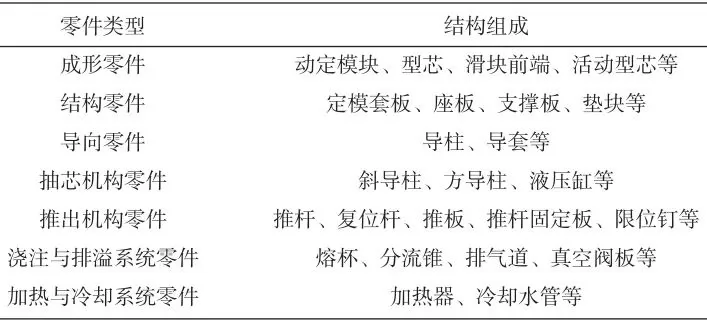
Table 1 Basic structure and composition of die-casting mold
02Structural optimization of large die-casting mold parts
2.1 Structural design of dynamic and fixed modules
2.1.1 The dynamic and fixed module adopts a mosaic structure
The forming part is the core part of the die-casting mold, and its structure is mainly determined by the shape and processing technology of the die-casting part. The formed parts are subjected to high-pressure and high-speed molten metal impact during the die-casting process, so the design must ensure sufficient strength, stiffness and toughness. Considering the characteristics of large die-casting molds, under the premise of ensuring strength and rigidity, the formed parts should be divided according to function or process as much as possible, and the inlaid structure should be adopted. The advantages of the inlaid structure of the large die-casting die movable and fixed modules are as follows.
(1) According to the functional requirements, the reasonable use of die steel can reduce the cost of the die. As shown in Figure 1, module A is the part forming area, with complex shape and high surface quality, so imported high-quality hot work die steel (W350, DIEVAR, etc.) is used, and module B is in contact with the gating system, and ordinary die steel ( H13).
(2) According to the complexity and vulnerability of the cavity, splicing and splicing can improve the processing technology and facilitate replacement. At the same time, maintenance is convenient and fast, and it does not affect the overall performance of the mold.
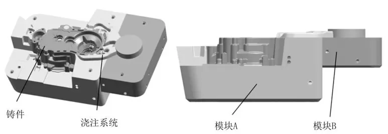
Figure 1 Block structure
(3) For special structures such as forming size and shape, the use of inlaid structure is conducive to the implementation of the local forced cooling scheme of the mold, and is conducive to the exhaust of the cavity.
(4) The use of mosaic structure for large-sized cavities can reduce the difficulty of processing and prevent defects such as cavity cracking and deformation.
2.1.2 Outline structure of dynamic and fixed module
In the continuous production process of the mold, the temperature of the cavity will be higher than the temperature of the sleeve, which will cause the expansion of the forming module to be greater than the expansion of the sleeve, and the H7/g6 matching gap between the sleeve and the cavity cannot resist the change of thermal expansion. thermal deformation will occur. The larger the cavity module size, the greater the deformation. In order to solve this problem, the shape of the cavity module adopts the structure of Figure 2. The two adjacent straight surfaces are used as positioning reference surfaces, and the other adjacent two surfaces are made into inclined surfaces. After the insert is heated and expanded, the horizontal expansion of the parting surface can be determined by the vertical direction. Release, can effectively solve the problem of template expansion and deformation, generally α is 6°. At the same time, when designing the shape of the forming module, the surrounding and bottom surfaces of the module adopt large rounded transitions to ensure that the strength of the sleeve is not damaged.
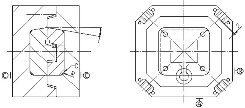
Figure 2 Assembly of inserts and sleeves
2.2 Square guide post guide bush
For large molds, due to the large center-to-center distance between the guide posts and guide sleeves arranged on the edge of the mold, under different heating conditions of the moving and static molds, the amount of expansion will be different. When the change is high, the guide post and guide sleeve will produce abnormal noise or even surface strain, which will affect the mold matching accuracy. Therefore, the large mold adopts the structure of the square guide post and guide sleeve, the sliding fit of H9/e8 is adopted in the direction of small thermal expansion, and the gap of 2 mm is adopted in the direction of large thermal expansion. Because the mold temperature field radiates radially from the cavity as the center, the square guide column guide sleeve is generally arranged at the four corners of the mold sleeve plate, and the direction and clearance value are determined as shown in Figure 3.
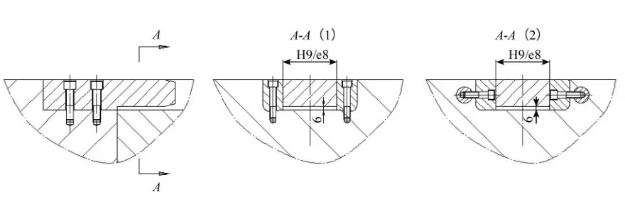
Figure 3 Square guide post and guide sleeve structure
2.3 Design of Diverter Cone and Melt Cup
The diameter of the large mold material cylinder is large, and to ensure the effective transmission of the boost pressure, the material cake needs to have a sufficient thickness. Due to the mismatch between the large volume of the material cake and the cooling rate of the casting, the mold retention time is prolonged, the production cycle is prolonged, and the material cake often bursts when the mold is opened and the parts are taken out, so the cooling of the split cone and the melting cup must be increased. , in order to effectively shorten the cooling time of the cake and improve the production efficiency. Figure 4 shows the optimized split cone and cup structure.
2.3.1 Diverter cone structure
Try to design a diverter cone in a large die-casting mold, which can reduce the length of the melt cup and the push-out stroke of the injection punch. The inside of the shunt cone is processed into a large cavity, the volume of the cooling water channel is increased, and the single-sided wall thickness is guaranteed to be >25 mm according to the strength calculation. The cooling water adopts a single-point independent nozzle water cooling method. The inner wall of the stainless steel water pipe enters the water and the outer wall returns water, and the diameter (cross-sectional area) of the inlet and outlet water pipes is increased to ensure sufficient cooling water flow to achieve rapid cooling. The cooling water return end is connected to the external flow valve of the mold. During the trial production, an infrared camera is used to monitor the mold temperature at the shunt cone, and the flow valve at the return end is adjusted according to the mold temperature, and finally the management value of the cooling water flow is locked. In mass production, the cooling stability of the split cone is ensured by monitoring the flow value of the cooling water.
2.3.2 Melt cup structure
The melting cup adopts a two-piece structure, and the length of the front end of the melting cup only needs to meet the height of the material cake, which is not only conducive to arranging cooling water at the front end of the melting cup to speed up the cooling of the material cake, but also ensures the advantages of an integrated material cylinder. The head runs stably and reliably.
The front end of the melting cup uses a special fixture to machine a V-shaped hole along the periphery of the hole on the machining center (as shown in Figure 4), which increases the length and surface area of the cooling water channel; the rear end of the melting cup adopts a conventional cooling water channel. The adjustment and use of cooling water are the same as above.
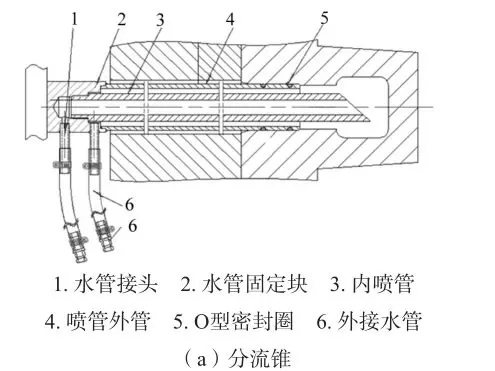
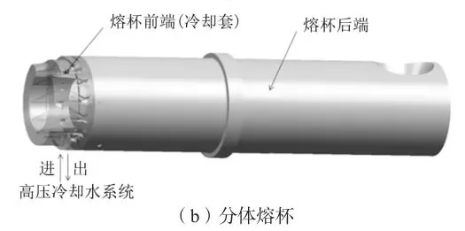
Figure 4 Structure of split cone and split melt cup
2.4 Design of core pulling cylinder
Because the hydraulic core-pulling mechanism can achieve the characteristics of large pulling resistance and long core-pulling stroke, the slider of large die-casting molds generally adopts a hydraulic core-pulling mechanism. The structural characteristics of the large die-casting die determine that the slider will have a large size and a large core-pulling stroke. For these two situations, the structure of the core-pulling cylinder can be optimized as follows.
The size of the slider is large in the direction of the parting surface, and the double oil cylinder is used for core pulling. The double-cylinder core-pulling structure is shown in FIG. 5 , the cylinder piston rods 4 on both sides are fixed on the sleeve plate, and the cylinder block 1 is fixed on the cylinder connecting plate 2 . When working, the piston rod 4 is fixed, and the cylinder block 1 drives the slider to move through the cylinder connecting plate 2. When the front end without rod cavity enters the oil, the oil cylinder drives the slider to pull the core; on the contrary, when the rod cavity enters the oil, the oil cylinder drives the slider to insert the core. The mold adopts double oil cylinder structure, which can not only reduce the diameter of the oil cylinder, but also make the operation of the more important two-sided force slider more stable.
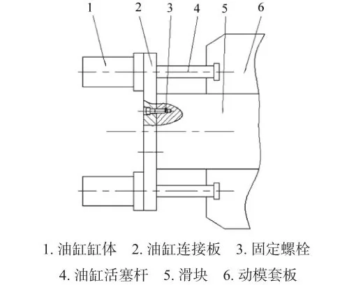
Figure 5 Double-cylinder core-pulling structure
When the core pulling force of the slider is large and the stroke is large, a composite oil cylinder is used. The structure of the composite core-pulling cylinder is shown in Figure 6. Part 2 is both the cylinder block of the small cylinder and the piston rod of the large cylinder. During operation, due to the large initial core pulling force of the slider, the large cylinder needs to be started first. When the forming surface of the slider is separated from the cavity, the core pulling force is only the friction force of the movement, and the small oil cylinder can drive the core pulling stroke to complete. When the core is pulled, oil is fed into the lower oil port. When the large cylinder piston rod 2 drives the slider to move to the left for the L1 stroke, the large cylinder stops running, and the small cylinder piston rod 5 drives the slider to continue to move to the left for the L2 stroke. The mold adopts the structure of composite core-pulling cylinder, which can not only meet the large core-pulling force of the large cylinder, but also avoid the problem of slow core-pulling speed due to the large volume and slow oil feeding speed of the large cylinder, which can reduce the production tact and improve the production efficiency. .
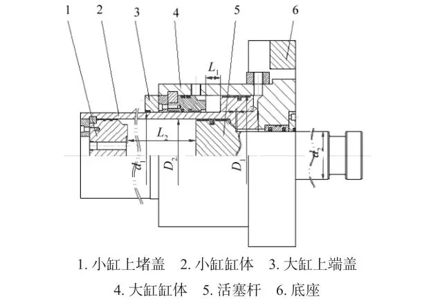
Figure 6 Structure of composite core-pulling cylinder
2.5 Design of local booster mechanism
With the enlargement and integration of products, the structure and shape of die castings are becoming more and more complex, and thin-walled parts with uneven wall thickness are increasing. At the same time, higher requirements are placed on the quality of castings. Low cost is the development trend. On the other hand, thin-walled castings will have difficulty in feeding at the hot joints of local wall thickness, and are prone to casting defects such as shrinkage cavities, resulting in the reduction of casting strength and the risk of leakage. The local pressurization technology is to set a pressurized oil cylinder on the die-casting mold to perform secondary pressurization on the hot joint of local wall thickness, so as to obtain a casting with dense structure and eliminate the generation of local shrinkage. The local pressure boosting mechanism can be adjusted according to the location at the hot joint of the casting.
It can be set on the static and dynamic mold or the side-drawn slider (Figure 7).
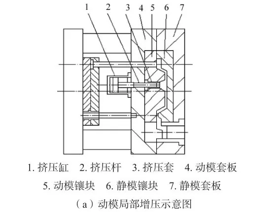
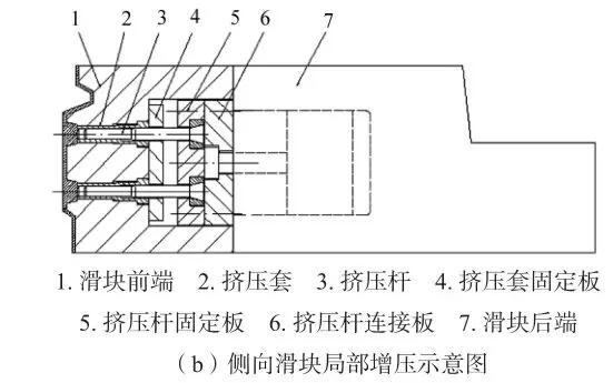
Figure 7 Local pressurization structure
03App Verification
The above optimization measures for molds have been applied to molds for die-casting machines of more than 2 000 t, such as automobile engine cylinder blocks, oil pans and gearbox casings. The processing difficulty and mold cost are reduced, and the production efficiency and mold life are improved. An application example is shown in Figure 8.
04 Conclusion
(1) Under the premise of ensuring strength and rigidity, the forming parts of large die-casting molds should be divided according to function or process as far as possible, and the inlaid structure should be adopted. The two sides of the outer edge of the insert are assembled with inclined surfaces, which can reduce the deformation caused by the thermal expansion of the mold.
(2) By optimizing the structure of the diverter cone and the melting cup, and increasing the cooling of the casting material cake, the production tact can be reduced and the efficiency can be improved.
(3) The large-scale die-casting mold adopts square guide column guide sleeve, which can ensure the guide accuracy of the mold under different heating conditions of the dynamic and static molds.
(4) The hydraulic core-pulling mechanism adopts double oil cylinders to ensure the smooth operation of the large-sized sliders, and the use of composite oil cylinders can improve the running speed of the sliders, thereby improving production efficiency.
(5) The local pressurization mechanism can effectively solve the shrinkage cavity at the hot joint of the casting, and can be set on the static and dynamic mold of the mold or the slider.

.png)


.png)
.png)
.png)

.png)


.png)

.png)

 +86-574-83008051
 sales@innovaw.com


.png)