In die casting mold runner design, tapered runner design is more common. The tapered runner is composed of sprue, cross runner, triangular area, inner gate, and buffer package, as shown in Figure 1.
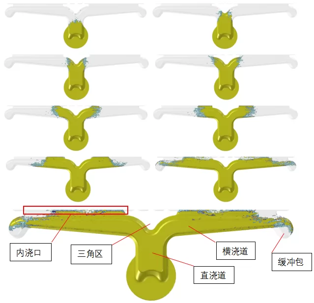
Figure 1. Zhizhu Chaoyun simulates the filling process of molten metal in the conical channel
And, from the sprue to the inner gate, the cross-sectional area is gradually reduced, as shown in Figure 2, N1>R1>(R2+R3)>(G1+G2), and N1≈1.25~1.7(G1 +G2).
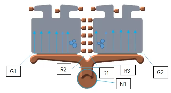
Figure 2. Expected flow of molten metal
The benefits of this design are:
1. Ensure that the molten metal in the entire gating system is in a full state, effectively reduce gas entrapment, speed up the flow of molten metal, and help complete the filling before the metal is solidified;
2. The set buffer package can be used to absorb the impact energy of molten metal and accept cold and dirty molten metal;
3. This type of gating system is light and handy, which can save the consumption of molten metal.
Next, I will use Zhizhu Chaoyun to simulate the filling process of molten metal in the conical runner, and understand the reasons for the variable cross-section design of the runner and the direct embodiment of the absorption function of the buffer package.
It can be seen from the filling process shown in Figure 1 that the molten metal always gradually reaches the inner gate in a state of being filled with the runner, and will not form a roll in the runner, and the molten metal at the forefront also flows into the buffer package, which is effective Avoid cold and dirty metal from entering the cavity.
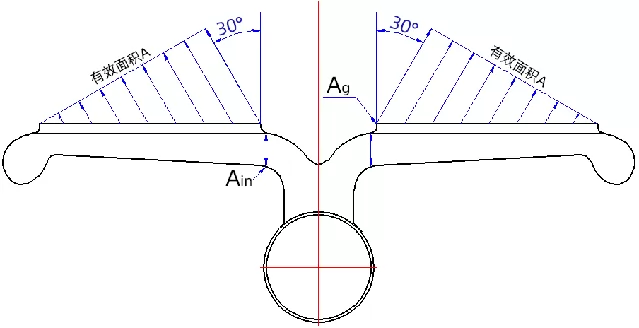
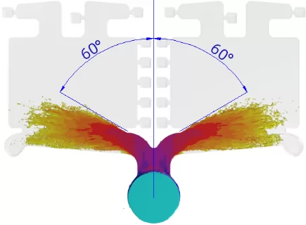
The casting structure shown in Figure 2 is a typical tapered runner structure. Although we all expect the molten metal to enter the cavity in the direction shown in the figure, after actual production verification, the die casting will always be in the place indicated in the figure. Air trapping occurs, which indicates a phenomenon: In the design of the tapered runner, the jet of molten metal enters the cavity at a certain angle, rather than at a right angle. The angle formed by the entering direction of the molten metal and the direction of gravity is also called the "jet angle", as shown in Figure 3.
The angle of the jet is determined by two factors:
1. Horizontal sub-velocity along the direction of the flow channel;
2. Vertical sub-velocity due to metal pressure.
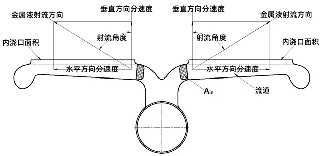
Figure 3. Jet angle
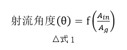
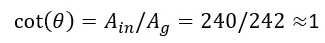
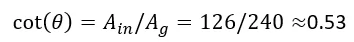
To be precise, it is the cross-sectional area at the entrance of the runner and the area of the inner gate that determine the size of the jet angle. The relationship between these three can be shown by Equation 1 and Figure 4.
The shape parameters of the runner system of the casting in this example are:
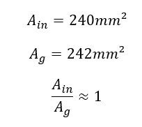
Combining Figure 4: Jet angle-cross-runner cross-sectional area/in gate relationship diagram, the specific jet angle value can be determined to be 45°.
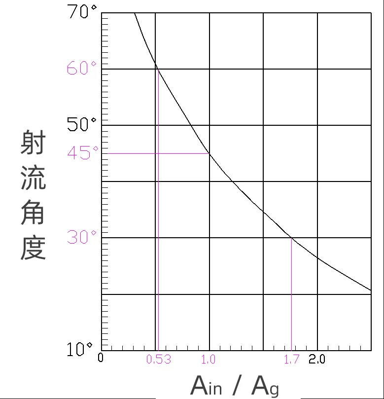
Figure 4. Determining the jet angle
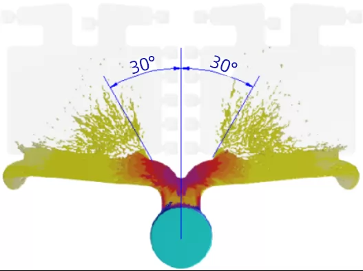
From the relationship expressed by Equation 1, it can be concluded that if the size of the inner gate is kept unchanged, when the size of the runner entrance becomes larger in the positive direction, the jet angle will be larger.
In order to express this change process intuitively, the corresponding casting model can be designed by setting different ratios, and the change process can be observed through the calculation results of die-casting simulation software.
Model one
Theoretical diagram:
Zhizhu Chaoyun simulation icon:
Model two
Theoretical diagram:
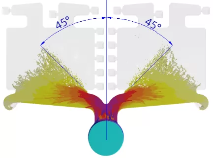
Filling completion time: 0.0152s
Theoretical diagram:
Filling completion time: 0.0263s
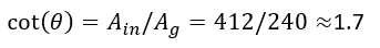
In addition, in the design of the tapered runner structure, the effective area of the inner gate also needs to be considered, because the size of the jet angle also affects the effective area value of the inner gate. The jet angle has the following relationship with the effective area and actual area of the inner gate:
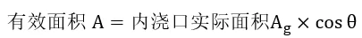
It can be seen from the comparison of the above three models that under the same internal gate area condition, the effective area will be reduced if the jet angle is large, that is, the actual filling time will be longer than the theoretically designed filling time, and the castings will appear cold lines, The probability of flow marks will be higher than expected.

.png)


.png)
.png)
.png)

.png)


.png)

.png)

 +86-574-83008051
 sales@innovaw.com


.png)