Aiming at the problem that the die-casting machine with a clamping force of 25 000 kN has a low expansion ratio and impacts during mold opening and closing, a study on the optimization design of the machine hinge system was carried out. First, the mechanical model of the clamping mechanism is established, the structural stress, deformation and stiffness are calculated by the finite element method, and the strength is checked. Using the stiffness of the toggle link as a parameter, a rigid-flexible multi-body dynamics model of the hinge system is established. The simulation and test results are consistent, which verifies the accuracy of the modeling method. Finally, on the basis of the multi-body dynamics model, an optimal design model was established by taking the coordinates of the toggle link hinge point as the design variable. Comparing the optimized design with the original design, the force expansion ratio has been increased from 21.45 to 24.57, the stroke ratio has been increased from 1.03 to 1.08, and the impact force of the mold clamping process has been significantly reduced.
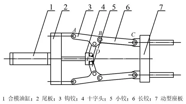
Die casting machine is the basic equipment for pressure casting of non-ferrous metals and their alloys, with a complex structure. The clamping mechanism is composed of a template and a hinge, and is the key mechanism of the die casting machine. Each die casting production cycle is accompanied by an opening and closing action of the mold clamping mechanism. The clamping and mold opening of the mold clamping mechanism are mainly driven by the hydraulic cylinder to push the hinge system. The structure is shown in Figure 1. The hinge system quickly expands the thrust of the oil cylinder and pushes the template to move. The machine hinge system is a typical multi-link mechanism. The unreasonable design of the toggle link (link) size leads to insufficient expansion of the mold clamping mechanism, large impact during mold clamping, low mold life, long mold opening and clamping time, and die-casting low efficiency. To achieve a large clamping force, it is necessary to increase the thrust of the cylinder, and the work energy consumption is high.
At present, the design of die-casting machine hinges is mainly based on theoretical calculation methods. Since it cannot take into account the influence of other complex structural parts in the clamping mechanism and the deformation of each part of the hinge system itself, the calculation results have large errors, leading to the design The hinge structure of the machine is unreasonable. Repeated design and manufacturing lead to long R&D cycles and high costs. The collaborative application of digital modeling, finite element method and kinematics simulation technology provides a brand-new solution for the design of die casting machine hinges. Through numerical simulation technology, not only the quantitative design of performance can be realized, but also the optimal design can be realized, which significantly reduces The research and development cycle of the hinge system saves costs.
Aiming at the actual problems of large-scale die-casting machines with a clamping force of 25 000 kN, which are reported by the company, which have large cylinders, high energy consumption, and high abnormal noises during each opening and closing of the mold, the defect cause analysis was carried out based on the numerical simulation method. Optimized design of hinge system. The stroke of the movable seat plate is improved, and the stroke of the oil cylinder is minimized at the same time, and smooth movement of the template during the mold opening and closing process is realized without pause and noise.
1 Finite element modeling of clamping mechanism
A 3D assembly model of the die-casting machine clamping mechanism with a clamping force of 25 000 kN was established. The materials of the components were QT500 and No. 45 steel. The physical properties of the materials are shown in Table 1. Discretize the components in the assembly model respectively, define the contact relationship and friction factor and other parameters between the connected components, apply a corresponding load of 25 000 kN, and constrain the degree of freedom of displacement of the shaped seat plate to establish The mechanical model of the clamping mechanism is shown in Figure 2.
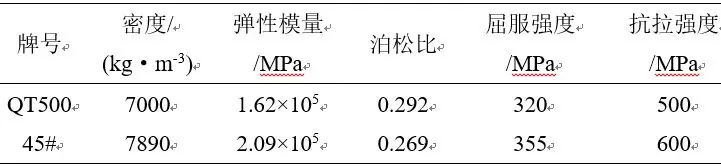
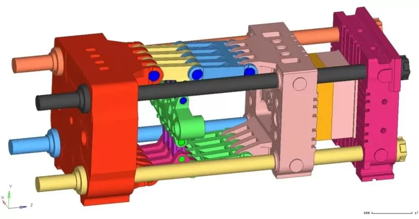
Figure 2 Mechanical model of clamping mechanism
Solve the above-mentioned mechanical model, and obtain the overall displacement cloud diagram and stress of the clamping mechanism, as shown in Figure 3 and Figure 4. Through the post-processing of the numerical simulation results, the horizontal and vertical stiffnesses of the tail plate, the hinge system, the elder pillar, the movable seat plate and the mold, and the fixed seat plate system in the horizontal and vertical directions are calculated respectively, as shown in Table 2. The vertical stiffness of the system 1 indicates the vertical stiffness of the joint between the hinge system and the tail plate, and the vertical stiffness 2 indicates the vertical stiffness of the joint between the hinge system and the movable seat plate.
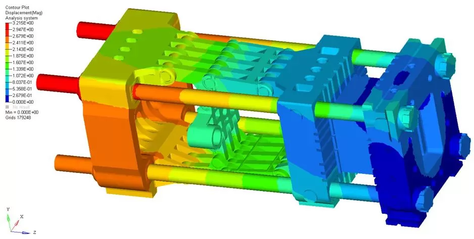
Figure 3 Displacement cloud diagram of clamping mechanism
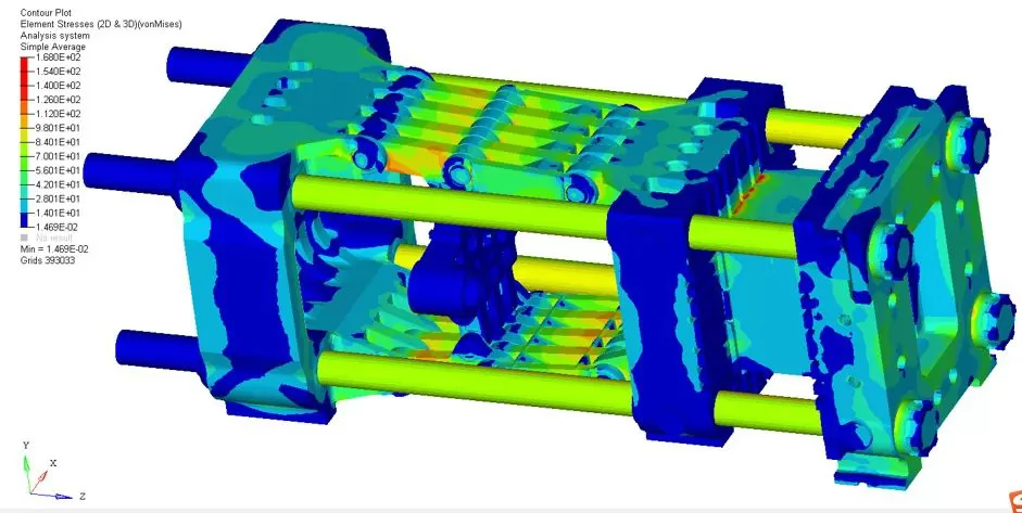
Figure 4 Stress cloud diagram of clamping mechanism
It can be seen from the displacement cloud diagram that the maximum displacement of the mold clamping mechanism is 3.22 mm, which is located at the end of the Collin column near the tail plate. Regardless of the local stress at the contact boundary of the unit, the maximum stress of the mold clamping mechanism is 118 MPa, which is located inside the joint between the hinge and the tail plate, which is much less than the yield strength of the material 320 MPa, so the overall structure of the mold clamping mechanism can meet the strength design requirements.
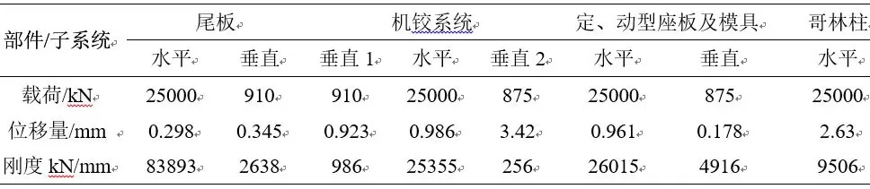
Table 2 Rigidity of parts and subsystems of clamping mechanism
2 Multi-body mechanics modeling of machine hinge system
Figure 5 shows the hinge system of a 25 000 kN die-casting machine. It is a typical double-toggle 5-joint structure. The crosshead, small hinge, hook hinge and long hinge are used as toggle levers, and each toggle lever is connected by a rotating shaft. A , B, C, D, E are the hinge points between the hook hinge and the tail plate, the long hinge and the hook hinge, the movable seat plate and the hook hinge, the hook hinge and the small hinge, and the small hinge and the cross head in the upper half hinge. According to the structure and working mechanism of the hinge system, the geometric relationship of its motion is established as shown in Figure 5.
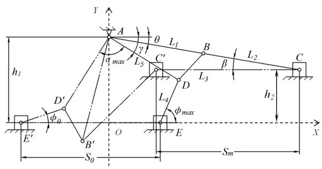
Figure 5 Schematic diagram of the movement relationship of the hinge system
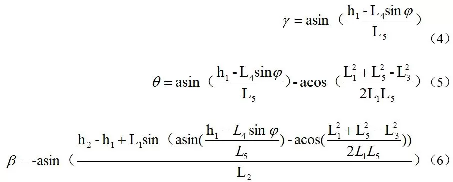
When the cylinder pushes each toggle lever to move to a predetermined state, the hinge system establishes a coordinate system as shown in Figure 5. O is the intersection of point A and the horizontal symmetry axis of the hinge system. According to the rigid body analysis mechanics, the parameters β, γ, φ, The θ parameter geometric equation is
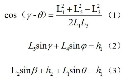
In the formula, L1 is the distance between A and B hinge points, mm; L2 is the distance between B and C hinge points, mm; L3 is the distance between B and D hinge points, mm; L4 is D, E The distance between hinge points, mm; L5 is the distance between A and D hinge points, mm; h1 is the distance between A and E hinge points, mm; αmax is the maximum opening angle, °; β is the hinge point BC is the angle in the horizontal direction, °; γ is the angle between the hinge point AB and AD, °; θ is the oblique arrangement angle, °; φ is the angle between the hinge point DE and the horizontal direction, °.
Since the degree of freedom of the system is 1, and φ is selected as the generalized coordinate, the other variables are:
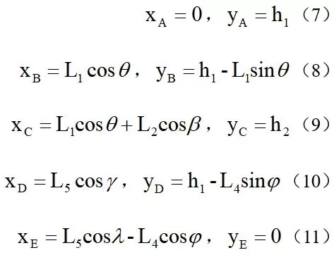
According to the coordinate system in Fig. 5, the coordinate equation of ABCDE point is:
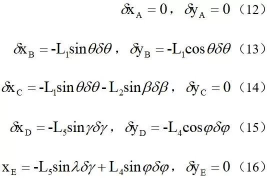
For the variation of the coordinate equation, the imaginary displacement of each point is:
The main power of the system to do the work to the system is:
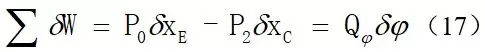
In the formula, P0 is the input force of the drive cylinder, kN; P2 is the clamping force, kN. Since the machine hinge system is a static balance system, the generalized force Q=0, the clamping force under the static force of the machine hinge rigid body system can be obtained as:
in:
The actual machine hinge system is a deformable system. Especially when the system moves close to the predetermined final position, the clamping output force increases sharply, and the compression deformation of the toggle lever causes each point to not reach the preset position, especially due to the large deformation of L2. Therefore, it is necessary to follow the flexible body computer hinge system, and the calculation process is shown in Figure 6. Taking into account the deformation of each toggle lever, L2 is considered as a flexible body for calculation. When φ becomes, β becomes, the new position point is calculated by iteration, and the generalized force is calculated based on the principle of virtual displacement until it reaches the preset position of clamping, and the generalized variable φ is finally.
Figure 6 Flow chart of mold clamping force calculation
However, when calculating the mold clamping output force according to Fig. 6, due to the iterative cycle, the calculation workload is relatively large. In actual engineering, simulation software is used to iteratively calculate the final mold clamping force to be Pn. The expansion factor M is:
During the mold clamping process, the ratio of the stroke Sm of the movable seat plate to the stroke S0 of the driving cylinder piston is the stroke ratio, the ratio of the speed Vm of the movable seat plate to the speed V0 of the driving cylinder piston is the speed ratio, the stroke ratio KS and speed The KV expression is:
Numerical simulation of 3-machine hinge system performance
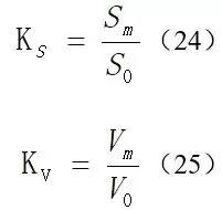
The virtual prototype model of the die-casting machine hinge system is established in the multi-body dynamics simulation software. Since the hinge system structure is a symmetrical structure from top to bottom, the 1/2 model is used as the research object, combined with the clamping mechanism components and sub-units calculated by the finite element method. The system stiffness results, and the simplified kinematics simulation model of the rigid-flexible hinge system is established as shown in Figure 7.
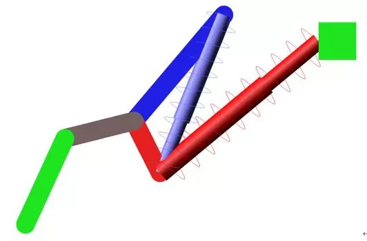
Figure 7 Kinematics simulation model of machine hinge system
Simplify the hook hinge and the long hinge into a spring system. The components are constrained by the rotation pair, and the corresponding friction factor and component quality are set to apply the driving load at the crosshead drive cylinder. The angle between the hook hinge and the long hinge is measured, and the movable seat The thrust, displacement and speed of the plate. The kinematics model of the hinge system is solved, and the angle curve of the toggle lever, the curve of the hinge expansion force, the stroke ratio curve and the speed ratio curve are shown in Figure 8.
From the force expansion curve of the simulation results, it can be seen that the angle between the hook hinge and the long hinge gradually increases during the process of the machine hinge system from contracting to unfolding, and finally reaches 180°, and the mold is locked. During the process of machine hinge expansion, it is necessary to overcome the effect of friction. The initial force expansion ratio gradually changes from a negative value to a positive value. When the hinge is close to the clamping state, the slope of the force expansion ratio curve increases sharply, indicating that the force expansion ratio increases rapidly to the maximum The value is 21.45. Correspondingly, it can be seen from the stroke ratio curve that starting from the selected simulation initial state, the stroke ratio increases rapidly at the beginning of the hinge unfolding process, and reaches the maximum at a position close to 1/2 of the total stroke. The maximum value is 1.39. The ratio gradually decreases, and the stroke ratio drops to 1.03 when it is close to the clamping state. It can be seen from the speed ratio curve that the speed ratio increases rapidly in the initial stage of the hinge unfolding process, and reaches the maximum at the position close to 1/2 of the total stroke, and the maximum value is 1.60. After that, the speed ratio decreases rapidly, and the speed ratio decreases when it is close to the clamping state. To 0, it can effectively reduce the impact of the mold on the template and increase the service life of the die casting machine and the mold.
Using the Swiss Sensormate DU-4D Collin column tester, the clamping force of the DM2500 die-casting machine of a certain company is tested to be 27 540 kN, the driving cylinder pressure is 16 MPa, and the cylinder diameter is 320 mm. The expansion of the DM2500 die-casting machine is calculated. The force multiple is 21.40, and the simulated force expansion result is 21.45, which is close to the actual situation. Therefore, the numerical simulation method is reliable.
Optimized design of 4-machine hinge system
Force expansion ratio, stroke ratio and speed ratio are the key index parameters of the machine hinge system. The optimization design goal of the machine hinge system is to have a larger force expansion coefficient and stroke ratio in the clamping state. During the unfolding process of the machine hinge system The speed in the middle of the stroke is relatively large, and the speed in the beginning and the end of the stroke (close to the clamping state) is relatively small. The machine hinge system is a typical multi-link mechanism. Without changing the number of toggle levers and the hinged position of the toggle lever with the movable seat plate and the tail plate, the main influencing factors of the system performance are the length and stiffness of each toggle lever. The plane coordinate values of the three toggle link joints B, D, and E in Figure 5 are respectively used as design variables, as shown in Table 3. The design variables are used to control the length of each toggle to optimize the design of the machine hinge system.
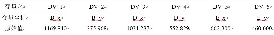
Table 3 Design variable table
Carry out design research and calculate the sensitivity of all design variables to the performance of the hinge system. Taking the original value of the above design variables as the median value, and deviating from 5% to 10% to the left and right sides as the design space and constraint conditions, the kinematics simulation optimization model of the hinge system is solved. The sensitivity of the design variables to the design targets is shown in Table 4.
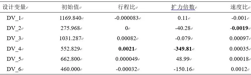
Table 4 Sensitivity of design variables to design goals
From the sensitivity calculation results, it can be seen that the stroke ratio and expansion ratio are the most sensitive to the change of the design variable DV_4, while the speed ratio is the most sensitive to the change of the design variable DV_2. Then select the test strategy, conduct the design of experiment (DOE) and optimize the design. The design variables before and after the optimization and the performance indicators of the hinge system are shown in Table 5. The curves of the force expansion ratio, stroke ratio and speed ratio of the hinge system before and after optimization are shown in Table 5. See Figure 9.
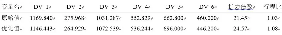
Table 5 Coordinates of toggle lever hinge points
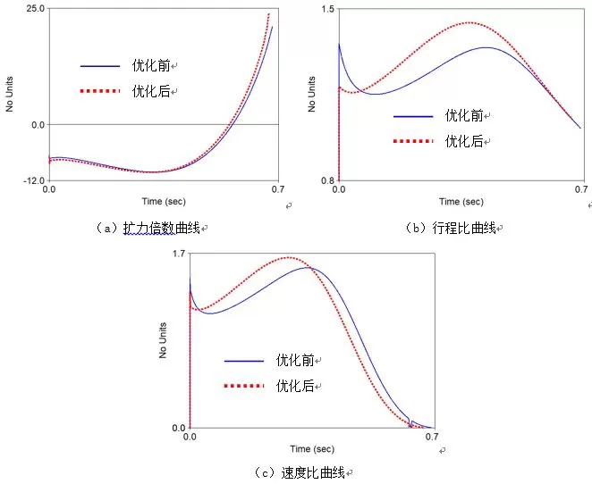
Figure 9 Comparison curve of the performance index of the hinge system before and after optimization
It can be seen from the comparison curve of the performance index of the hinge system before and after the optimization that the optimized expansion ratio reached 24.57, which was 14.5% higher than the 21.45 before optimization. Under the condition of the same drive cylinder diameter and pressure, the maximum die-casting machine The clamping force can reach 31 546 kN. If the original clamping force is maintained, the pressure of the drive cylinder can be reduced correspondingly to achieve energy saving and consumption reduction. The optimized stroke ratio is 1.08, which is an increase of 4.85% compared with 1.03 before optimization. The change is not obvious. However, the optimized stroke is lower than the front section of the curve, and is smoother, and the middle section is higher. Compared with the optimization before, it can shorten the combined stroke. Mold time, to avoid the impact of the drive cylinder and the hinge when the hinge system is contracted to the first part of the unfolding process. Compared with the curve, the optimized speed has the characteristics of smooth front section, higher middle section, lower and smoother end section, indicating that the optimized movable seat plate has lower initial speed and higher middle speed than the optimized pre-clamping process, and it is close to lock. The mold speed is lower, which can effectively avoid the impact of the driving cylinder and the template, and improve the reliability and performance of the mold and the die-casting machine.
5 Conclusion
(1) The deformation of the toggle lever has a great influence on the performance of the hinge system. The design process of the hinge system should consider the influence of the deformation of the toggle lever.
(2) Calculate the rigidity and strength of the clamping mechanism by the finite element method. When the clamping force is 25,000 kN, the maximum local stress of the clamping mechanism is 118 MPa, and the overall structure meets the strength design requirements.
(3) Considering the influence of toggle lever deformation, based on rigid-flexible combined multi-body dynamic modeling and kinematics simulation calculation, the force expansion ratio of the hinge system is 21.45, which is close to the experimental test result of 21.40, and the numerical model is reliable.
(4) The hinge system can be optimized by optimizing the space position of the toggle lever hinge point of the die casting machine. The optimized design of the hinge system has a force expansion ratio of 24.57 and a stroke ratio of 1.08, which is 14.5% and 4.85% higher than before optimization. , The driving cylinder, hinge system, template and mold are less impacted during the clamping process.

.png)


.png)
.png)
.png)

.png)


.png)

.png)

 +86-574-83008051
 sales@innovaw.com


.png)