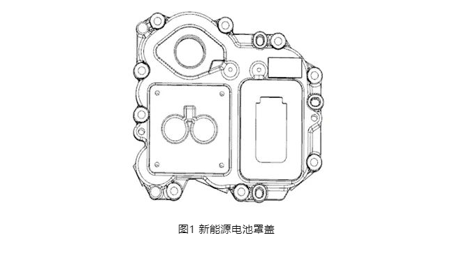
1. Product structure
The shape of the new energy vehicle battery cover is made of AlSi10MnMg. The average wall thickness of the product is 3 mm, the outline size is 152 mm×142 mm×22 mm, the projected area of the casting is 142 cm2, and the mass is 0.22kg. This product is assembled on the upper cover of the battery, with multiple sensors and bolts mounted on the outer surface. The product function needs to protect the internal battery pack and prevent liquid leakage. At the same time, it needs to withstand certain external impacts and resist long-term fatigue vibration. Internal control requires that the tensile strength is greater than 300 MPa, the yield strength is greater than 210 MPa, the elongation is greater than 5%, the processed surface cannot have shrinkage holes greater than 1 mm, and the sealing test condition is that the leakage rate is less than 8 mL/min under 10 kPa. The as-cast tensile strength of this alloy is 240 MPa, the yield strength is 140 MPa, and the elongation is 5%, which cannot meet the demand. Therefore, it needs to be improved from the aspects of raw material composition, mold design and artificial aging.
2. Chemical composition analysis
AlSi10MnMg is based on Silafont-36 and complies with the DIN EN 1706 standard. The chemical composition is shown in Table 1. The Si content is slightly lower than the AlSi eutectic alloy and has better fluidity. The low Fe content eliminates the needle plate block of the Al-Fe-Si phase, and the die casting is less likely to crack under stress. A certain Mn content can weaken the harm of Fe, prevent the alloy from sticking to the mold during die casting, and present a spherical phase in the structure.
In the AlSi10MnMg aluminum alloy specified in the standard, the Mg content is 0.1%~0.6%, which is a relatively wide range. Wu Shusen et al. found that the increase in Mg content is positively correlated with tensile strength and yield limit, and negatively correlated with elongation. Mg that is too low cannot produce sufficient strength and is not conducive to subsequent heat treatment, while Mg that is too high can lead to a reduction in elongation. Mg and Si form the Mg2Si strengthening phase, which causes the α-Al solid solution crystal lattice to be distorted, thereby causing to strengthen the alloy. Mg content of 0.20%~0.40% can achieve better comprehensive mechanical properties.
Fe is a harmful element in die-cast aluminum alloys. It exists in the flake or needle-like structure of FeAl3 and Al-Si-Fe, which reduces the mechanical properties of the alloy. The Fe content should be less than 0.15%. Mn element can form compounds with Fe. , to further eliminate the harmful factors of iron, and at the same time, Mn can increase the spherical crystal structure content of the product, keeping the Mn content at 0.50%~0.80%.
Appropriately increasing Ti can significantly refine the grain structure of aluminum alloys, improve the mechanical properties of the alloy, and reduce the tendency of alloy hot cracking. Therefore, the Ti content is controlled between 0.06% and 0.10%.
3. Mold design and numerical simulation
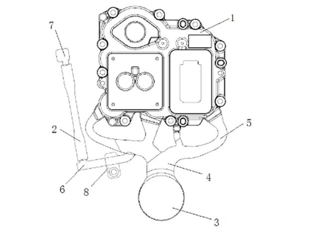
Figure 2 shows the basic structure of the battery cover pouring system. The total projected area is 290 c㎡, and the total pouring mass is 0.78 kg. The UB350ic die-casting machine is selected, and the clamping force of this equipment is 3500 kN. The design mold is 1 piece per mold, the diameter of the pressure chamber is ø60mm, and the filling degree of the material cylinder is 35%. The mold has five branch sprues, of which the left branch sprue manufactures the test piece 2 accompanying the casting, and controls whether the test piece needs to be manufactured through the blocker 8. According to the requirements of this product, components such as sensors are installed in the "glasses hole" area on the lower left side of the casting, the "rectangular box" area on the lower right side, and the "round hole" area at the end of the casting. These three locations are through holes, and these areas are processed All final pores on the machined surface should be less than 0.6 mm. The four branch sprues of the casting are in a comb-like structure. The inner gate length is 75 mm, the gate thickness is 2.0 mm, which is 2/3 of the solidification modulus, and the total gate cross-sectional area is 150 m㎡. The average flow rate can be calculated is about 40 m/s. The die-casting mold adopts FS438 die-casting hot work mold steel, which has good hardenability, toughness, thermal strength, thermal fatigue performance, and small heat treatment deformation. The cooling medium is water, with programmable intermittent high-pressure point cooling of 10 kg/c㎡ used locally, and natural exhaust. The position of the slag bag and the design of the exhaust wave plate are determined through simulation analysis.
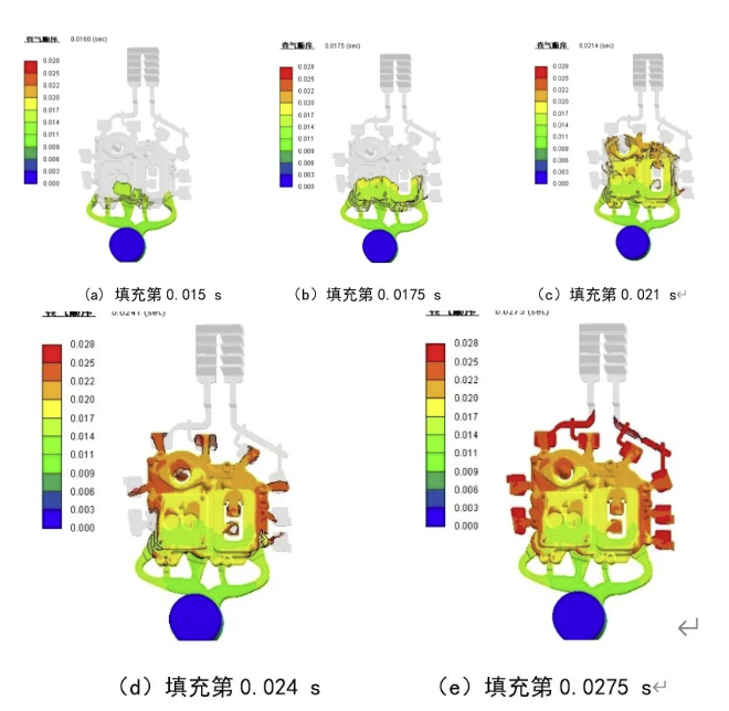
It can mainly carry out simulation analysis of mold filling, heat conduction, solidification process and stress field of casting. The simulation analysis objects are castings and die-casting molds, divided into 15.6 million grids. According to the high-speed filling characteristics of thin-walled parts, the initial boundary conditions are set as melt temperature 680 ℃, mold temperature 185 ℃, and punch filling speed 3.5 m/s, the heat transfer coefficient between the mold and the casting is 2 000 W/(㎡.K), and the heat transfer coefficient between the molds is 1 000 W/(㎡.K).
The simulation analysis results are shown in Figure 3. The alloy liquid reaches the inner gate at a low speed driven by the injection punch, and the aluminum liquid in the middle two gates is filled first. As can be seen from Figure 3a, high-speed injection starts at 0.015 s, the average gate speed is about 42 m/s, the aluminum liquid impacts the mold and core, and fills the cavity in a turbulent flow state. As can be seen from Figure 3b, the "glasses hole" area is reached at 0.0175 s. This part of the mold is for grinding and closing the mold core. The aluminum liquid will impact the core to generate vortex air entrainment. In order to ensure the quality of this important part, the design of the eyeglass hole through-hole was changed to a 2 mm thick blind hole, that is, the mold fit in this part was optimized to a 2 mm gap, and the air entrainment condition was significantly improved. The additional 2 mm material was added later. Sequential processing and removal. It can be seen from Figure 3c that the two streams of aluminum liquid reached the ends of the round hole and the rectangular hole respectively at about 0.021 s of filling. Through simulation, it was found that obvious air entrainment occurred at the end of the round hole and the end of the rectangular hole on the opposite side of the sprue, so they were designed separately. The slag bag is placed in round holes and rectangular holes, and the slag bag inlet is the intersection of simulated aluminum liquid; it is filled to the end of the casting at 0.024 s and flows to the slag bag around the casting, see Figure 3d. After multiple simulation analyses, eight slag bags were set up at the filling ends of the castings. X-rays after the castings were produced showed that the surrounding slag bags contained many shrinkage cavities and oxidized slag inclusions.
The "π" type exhaust wave plate is to isolate a traditional exhaust wave plate in the middle while keeping the ends connected. Generally, the isolation length on the left and right sides is 4 to 5 teeth. This structure can ensure that the gas discharge on the left and right sides is mutually exclusive. interference, while reducing space and saving processing and manufacturing costs. As can be seen from Figure 4, at this moment, the aluminum liquid on the left side reaches the first tooth button, and the right side is about to reach the first tooth button. Using particle tracking technology, the front end speed on the left side is measured to be 12 m/s, and on the right side is 1 3m/s. , since the average gap between the corrugated plates is 0.7 mm, the speed of the two liquid aluminum drops rapidly after passing through the first tooth buckle, and almost stops moving by the second tooth buckle. The final stop position of the aluminum liquid depends on the viscosity of the aluminum liquid, mold temperature, casting pressure, etc. Regarding the design, there are four independent tooth buckles on the left and right sides of the design, and the fifth to eighth tooth buckles are connected. Practice has proved that the design of the "π" type exhaust wave plate is reasonable and the production process is reliable.
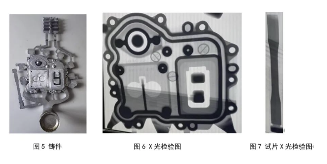
According to the simulation analysis results, the UB350iC die-casting machine was used to produce this part. The injection punch size is ø60 mm, and the measured gap between the punch and the material cylinder is 0.07 mm. In order to adapt to the filling of thin-walled parts, the temperature of the alloy liquid in the holding furnace is set to 680 ℃, the actual mold temperature is controlled between 180 and 200 ℃, the casting pressure is 80 MPa, the first-level injection speed is 0.2 m/s, and the second-level speed is 3.5 m/s. The casting is shown in Figure 5. Use the XG-160S T/S X-ray real-time imaging machine to check the internal quality of the part. It can be seen that the overall outline of the casting is clear, as shown in Figure 6. There are no visible pores, oxidized slag inclusions and other quality defects in important functional areas around the eyeglass hole, square hole and round hole. , The quality of the pouring end is good, and the circumferential sealing annular groove meets the design requirements. At the same time, the accompanying test piece has a clear outline and no visible pores and other defects, as shown in Figure 7. A WDW-50 electronic universal testing machine was used to measure the mechanical properties of the accompanying specimens. The average tensile strength was 260 MPa, the yield strength was 170 MPa, and the elongation was 6%. The performance could not meet the design requirements.
4. Heat treatment process effect
The purpose of heat treatment of aluminum alloy castings is to improve the mechanical properties of the alloy, enhance corrosion resistance, improve processing performance, and obtain dimensional stability. The age hardening of aluminum alloys not only depends on the composition and aging process of the alloy, but also depends on the defects of the alloy during the production process, especially the number and distribution of vacancies and dislocations. It is generally believed that age hardening is the segregation of solute atoms to form hardening. District results. AlSi10MnMg thin-walled die-casting parts can achieve better performance requirements under the appropriate process parameters of T5 and T6. Since the solution heat treatment process is more complex and higher temperatures can easily lead to out-of-deformation of thin-walled die-casting parts, and thin-walled parts can be uniformly dissolved in 2 hours, artificial aging treatment is performed with temperature as the variable.
The artificial aging temperature range is selected to be 170~210 ℃, with each interval of 10 ℃ as a group, and the holding time is 2 h. An Sx2-12-6 resistance furnace was used for artificial aging, with a rated power of 12 kW and a furnace size of 550 mm × 550 mm × 450 mm; each group of 3 test pieces was suspended and placed in the middle of the furnace, ventilated, and heated for 15 minutes. The aging temperature is specified, followed by automatic heat preservation timing, and finally the test piece is manually taken out and cooled in the air.
Use the WDW-50E universal tensile testing machine to conduct tensile testing at room temperature. The tensile testing process is in accordance with the national standard GB/T228.1-2010
After artificial aging heat treatment, the yield limit and tensile strength have been improved to varying degrees compared to the original cast state. At 190 ℃ The elongation first decreases and then increases. The elongation at 190 ℃ x 2h is 5.4%, but it is smaller than that of the die-cast blank.
The heat treatment aging temperature was further selected to be 190 ℃ and the heat preservation was held for 8 hours to de-age the battery cover casting. After the tensile test, the tensile strength was 307 MPa and the yield strength was 227 MPa, but the elongation dropped to 2.6%, indicating that Long heat treatment time has little effect on strength, but has a great effect on elongation.
5 Conclusion
Based on the AlSi10MnMg die-casting alloy material, in view of the mechanical performance requirements of new energy vehicle battery covers, a general method to solve this problem is proposed, namely, rational selection of alloy composition content, optimized design of die-casting molds, and correct configuration of artificial aging schemes. The results show that the Mg content in the alloy composition is 0.2%~0.4%, the overflow system is optimized according to the structural characteristics of the part, and the artificial aging is selected at 190 ℃ and 2 h, and its performance can meet the requirements.

.png)


.png)
.png)
.png)

.png)


.png)

.png)

 +86-574-83008051
 sales@innovaw.com


.png)