Summary
Taking the steel lower control arm of a mass-produced vehicle as the research object, through lightweight design, a steel-aluminum hybrid structure control arm with aluminum alloy castings as the core was developed, and the aluminum alloy castings were obtained through the extrusion casting process to achieve weight reduction. 25% set goals. Design and tests show that the steel-aluminum hybrid structure control arm with aluminum alloy castings as the core can meet the use requirements of the lower control arm, and greatly reduce the quality to meet the needs of the vehicle's lightweight.
As the demand for vehicle versatility increases, equipment such as electronics and high-quality safety systems continues to increase, resulting in increasing passenger vehicle weight. At the same time, globally, requirements for improving fuel efficiency and regulations for emissions are becoming more stringent. The goals of improving fuel efficiency and reducing emissions can be achieved by improving engine efficiency, reducing air and tire rolling resistance, downsizing the body, and reducing body mass. Achieving fuel efficiency and emission targets based on reducing overall vehicle mass is currently the easiest technical means to achieve. Therefore, how to reduce the quality of the whole vehicle has become one of the hotspots in the current engineering development.
Aluminum alloy has a series of characteristics such as light weight, high specific strength and good corrosion resistance, and has been widely used in the manufacture of front axle and cross member components. For lightweight design considerations, in order to reduce mass, the shape and size of the part are usually changed, and these changes can cause changes in the strength and toughness of the part, and lead to the failure of the part. Therefore, as a newly designed light alloy suspension part, careful consideration should be given to the structural design and material application, appropriate materials should be given appropriate functions, and only after multiple rounds of structural topology optimization analysis and forming process simulation can it be successful. .
This subject takes the steel plate punching and welding lower control arm of a mass-produced vehicle as the lightweight target. Based on the aluminum alloy and casting process, through the integrated design, it tries to realize the development of the lightweight control arm to meet the needs of the vehicle lightweight.
1 Target selection and analysis
Figure 1 shows the lower control arm of a mass-produced model of steel plate punching and welding. This control arm is selected as the goal of lightweight development, and aluminum alloy castings are used to replace the original components. The main requirements are as follows, the crash performance of the aluminum alloy control arm is comparable to the benchmark part. The absolute strength of aluminum alloy is lower than that of steel plate, but it can make full use of the advantages of the casting process. Through structural optimization, rib plates and reinforcing ribs are arranged to ensure that the structure meets the requirements of crash performance; compared with the replacement parts, the quality is reduced by 20% after changing the material. % or more; meet the corrosion resistance requirements of the OEM, which is equivalent to the corrosion resistance of the original steel parts. Installation requirements: It is required to meet the original installation conditions, and direct replacement can be realized. In the process of changing the local structure, the parts that have an assembly relationship with other components are not involved. After the structure adjustment, the original assembly relationship of the components remains unchanged, and the direct replacement assembly can be realized; while meeting the use requirements and lightweight goals, the cost of the components will not increase. more than 20%.
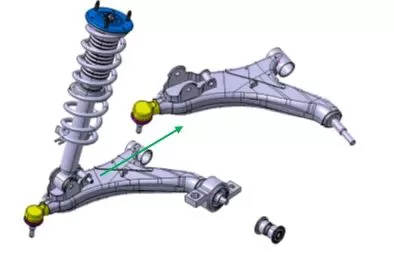
Figure 1: Steel plate punched lower control arm
With the requirement of lightweight of the whole vehicle, a variety of aluminum alloy control arms have been put into mass production, mainly using casting and forging. Although forging is currently the forming method with the highest mechanical properties, its production cost is high. Compared with forging, casting is a relatively economical forming method. The casting methods used for control arm production mainly include gravity casting, low pressure casting, differential pressure casting, squeeze casting and semi-solid casting. Taking into account factors such as production investment, product performance and production efficiency, the squeeze casting process with relatively close forging performance and better process stability was selected as the casting forming method in the development process.
2 Product design and analysis
2.1 Conceptual design of the product
Figure 2 illustrates the conceptual design scheme of the aluminum alloy control arm. Considering the characteristics of the squeeze casting process, the sand core cannot be used to form the cavity structure. It was decided to change the steel plate punching and welding control arm of the original cavity structure to an "H" structure aluminum alloy casting. By adding ribs and stiffeners, the overall rigidity of the casting was improved, and one-time casting was realized. Partially carry out structural changes and confirmation of connection methods.
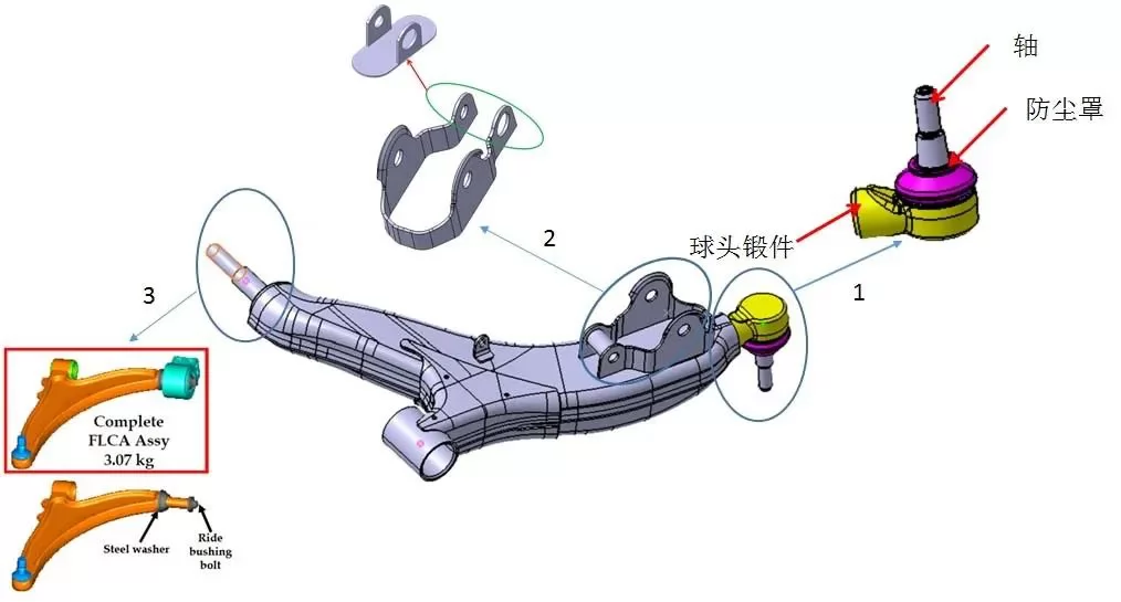
Figure 2: Conceptual design scheme of aluminum alloy control arm
At 1 in Figure 2, after the control arm is changed to an aluminum alloy casting, the connection method between the ball head assembly and the control arm will be changed from the original welding method to bolt connection. In order to meet the changed connection method, the structure of the ball head forging must be redesigned, and the prototype is completed by machining. Only the parts related to the ball joint of the connecting part are allowed to be changed, including the shaft, dustproof, ball bowl, snap ring, ball stud, and the structure of the clip and ball socket is not allowed to be changed.
In order to ensure the structural integrity of the casting, the performance of the casting process and the overall performance of the casting, it is confirmed that the original punched and welded shock absorber support is divided into two parts. The main support of the shock absorber is changed to an aluminum alloy design, and the integrated design is completed with the main body of the control arm. The shock absorber sub-support is still a punching and welding structure. The base is added on the basis of cutting the original parts, and the assembly is formed by welding. The assembly is connected with the aluminum alloy control arm by bolting. The structure of the assembly is suggested. 2 in Figure 2. The installation limit of the sub-support should be designed on the aluminum alloy control arm to ensure that the installation is in place.
In Fig. 2, all the parts in the original design are steel parts. After changing to aluminum alloy, the material of the shaft part is aluminum alloy, which is matched with steel parts. Under normal circumstances, aluminum alloy parts cannot occur with it. Direct friction fit. There are two solutions to consider. One is usually to add steel spacers to solve the problem of matching between aluminum parts and steel parts. After adding steel spacers, the size of the original design will change. It needs to be redesigned; the second is to borrow the original steel parts, redesign the structure of the connecting part, and realize the assembly of the parts through bolt connection.
2.2 Product design scheme
Figure 3. Design scheme of aluminum alloy control arm. Based on the original design of stamping and welding parts, the original surrounding assembly environment cannot be changed, and the structure and assembly of the original parts must be carefully considered. The overall design scheme is to replace the original upper plate, lower plate, connecting upper plate, connecting lower plate, bushing sleeve and shock absorber bracket to form an integral control arm with an integrated design "H" type aluminum alloy extruded control arm.
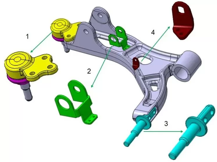
Figure 3: Design scheme of aluminum alloy control arm
At 1 in Figure 3, the ball head assembly adopts the original structure, but the original welding connection method is cancelled, and the connection plane design is added to the ball head forging, which is connected to the main body of the control arm by bolting, and the main body of the control arm is also correspondingly connected. The design of the connecting plane and connecting bolt holes. 2. Divide the shock absorber in the main body of the control arm in the punching and welding structure into two parts. The main part and the control arm are cast parts, and the rest is designed as a steel plate part, which is connected to the main body of the control arm by screws. The 3rd Division tried to integrate this part into the aluminum alloy casting in the conceptual design, but in the CAE analysis, it was found that the load of this part was large, and the structure could not be changed, so it was decided to keep the steel part of this part, in the steel part. The connecting structure is designed on the control part and the main body of the control arm, and then connected to the main body of the control arm through bolts. 4. The height sensor bracket in the original design cannot be integrated into the aluminum alloy casting, so it is necessary to maintain the design of the steel plate part and connect it with the main body of the control arm through screws.
2.3 Structural Analysis of Products
In order to ensure the correctness of the structural analysis results, the relevant material information of the control arm of the original steel plate punching and welding was obtained. The original control arm was constructed by welding 15 steel plate parts of different materials. Through the inquiry of relevant steel plate standards, the yield strength, breaking strength, elongation after fracture and Young's modulus of different steel plate materials used in the manufacture of punching welding control arms were obtained for CAE comparative analysis. The control arm has 7 working conditions: VERTICAL_BUMP, CORNERING, BRAKIING_REARWARD, MAX_BRAKING, MAX_ACCELERATION, LATERAL_SHOCK, CURB_PUSH. Considering that the fracture strength of the squeeze cast aluminum alloy AlSi7Mg-T6 is 220 MPa. During the analysis, it is required that the stress distribution in any area cannot be greater than 200 MPa. For the local stress concentration area, you can refer to the comparative stress in the original steel plate punching and welding design to ensure that when the new structural design structure is compared with the original structure for CAE comparative analysis, the stress of the aluminum alloy parts in the same part should not exceed 1/3 of the steel parts. .
Figure 4 shows the stress analysis results of the six working conditions, and it is found that the stress level can meet the use requirements of the components. In Fig. 4, the VERTICAL_BUMP, MAX_BRAKING and CONERING working conditions are non-destructive conditions, and their maximum stress does not exceed 200 MPa. After the analysis of the high stress parts, the stress concentration is mainly located in the bolt hole and the root of the shock absorber bearing. At the same time, the stress at the same position of the original steel part was compared, and the value did not exceed 1/3 of the stress at the same position of the steel part, so it was judged as qualified. For safety reasons, the rounded corners at the root of the shock absorber support are enlarged to reduce stress concentration.
Assembly inspection showed that the newly designed structure did not exceed the envelope surface of the original structure and could meet the installation conditions. In the process of changing the local structure of a component, there is no part that has an assembly relationship with other components. After the structure is adjusted, the assembly relationship of the component remains unchanged, and direct replacement assembly can be realized. Accordingly, design data is determined.
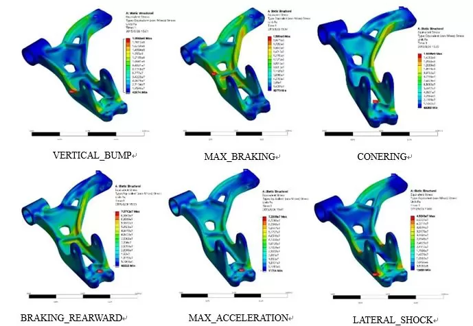
Figure 4: CAE stress analysis results under 6 working conditions
2.4 Summary of Product Design
Table 1 shows the quality comparison of the original structure and the newly designed structural components. The original upper plate, lower plate and connecting upper plate are replaced by the integrated control arm casting, and the original connection sleeve is borrowed. It can be seen from the quality data of the replaced steel parts and the integrated aluminum alloy control arm in Table 1 that after the aluminum alloy integrated casting is adopted, the quality decreases by 31%. The ball joint assembly and shaft borrow the original structure, but the structure of the connecting part is redesigned, and a bolt connection scheme is adopted.
The total mass of the original design structure is 4.358 kg, and the mass of the new design structure is 3.268 kg. It can be seen that the steel-aluminum hybrid structure formed by applying aluminum alloy-gold integrated castings and borrowing part of the original structural design can achieve the effect of reducing the weight of the component assembly by 25%, and achieve the predetermined weight reduction goal.
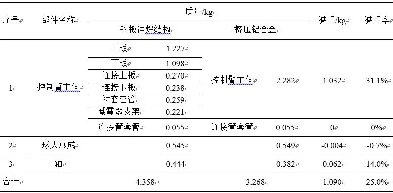
Table 1: Quality comparison of original structure and new design structural components
3 Process development and trial production
The basic design of the aluminum alloy control arm casting process is shown in Figure 5. Squeeze casting is carried out by a vertical extruder. The gating system consists of a material cake and a "Y"-shaped runner, and an overflow groove is set above the casting. The installation hole on the casting and the original structure shaft is formed by the core pulling on the left side. By setting the connecting hole formed on the upper part of the casting by core-pulling, it can be inserted before the mold is opened by the action of the setting oil cylinder, or inserted during the filling process, as an extrusion needle to eliminate casting defects. The mass of the control arm casting is 2.282 kg, the mass of the control arm cake and gating system is 4.250 kg, the mass of the overflow tank and the exhaust channel is 0.660 kg, and the total mass is 7.192 kg. The process yield is 31.7%, and the process yield is low. . Considering that the components are developed for trial production, the process yield has not been optimized. In actual production, one mold and two pieces can be considered to improve the process yield.
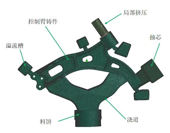
Figure 5: Schematic diagram of the casting process of the aluminum alloy control arm
ESI-ProCAST was used to simulate and analyze the casting process. Figure 6 shows the simulation results of casting defects without local extrusion and with local extrusion. It can be seen that in the case of not applying local extrusion, the local extrusion needle is inserted into the core for use; in the case of applying local extrusion, the local extrusion needle is not inserted into the mold first, and after the filling is completed, it is inserted into the mold. In the mold, the castings that have not been solidified are partially extruded to eliminate the internal defects of the castings. It can be seen from Figure 6a that there are still a certain number of defects at the part far from the gate and the part of the stiffener without applying local extrusion. Due to the solidification sequence of the castings, such defects cannot be eliminated by increasing dwell time and boost pressure. Defects that cannot be eliminated by increasing dwell time and boost pressure can be effectively eliminated by applying local extrusion techniques, see Figure 6b.
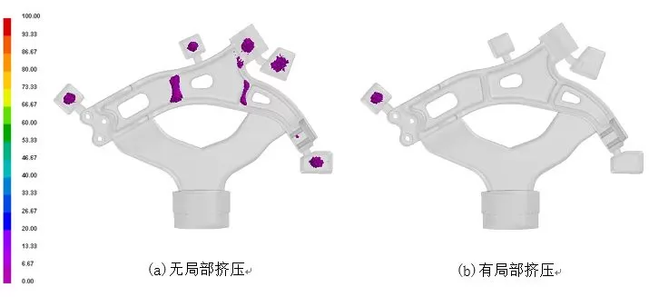
Figure 6: Defect simulation analysis results of the casting process
The aluminum alloy control arm is produced on a horizontal squeeze casting machine (SCH-1000A), and the mold is divided into two parts: a moving mold and a static mold. After the filling of the material cup is completed, the piston moves from bottom to top to complete the filling of the metal melt. In the movable die part, the connecting hole and the structure at the mounting surface of the connecting shaft are respectively formed by a core-pulling structure and a local extrusion and core-pulling structure. Two methods are used for casting production, one is without local extrusion, that is, the extrusion needle is pre-inserted into the mold to be used as the core; the other is local pressurization, that is, the extrusion needle is not inserted into the mold in advance, and the connection hole is formed originally The part will be filled with metal melt, and then under the action of the oil cylinder, the extrusion needle is inserted into the mold and acts on the casting to reduce the defects of the casting through its extrusion action. Take out the casting. Figure 7 shows the aluminum alloy control arm casting produced by squeeze casting.
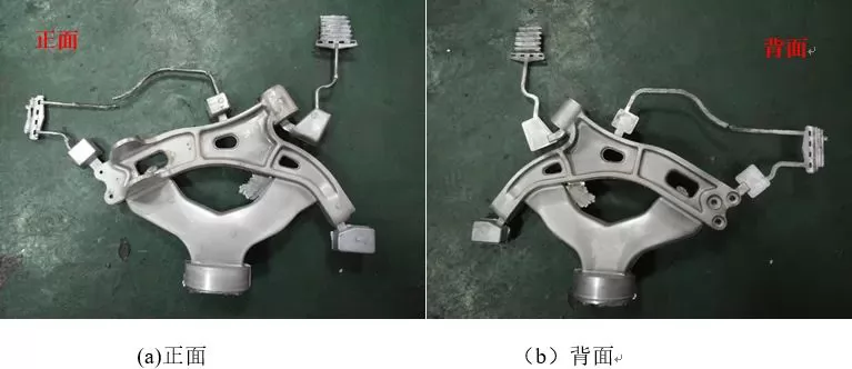
Figure 7: Aluminum alloy control arm casting produced by squeeze casting
Restricted by the size and structure of the casting, when sampling the body, according to the customer's requirements, several non-standard samples (based on GB T 228.1-2010) were taken from designated positions on multiple castings. The tensile test results are shown in Figure 8. The tensile strength was 293.2 MPa, the yield strength was 226.48 MPa, and the elongation was 9.01%, all of which were higher than the set values. In the later stage, the bench test, NVH test, loading test, crash test, durability test and other tests carried out in the main engine factory have all passed. It can be seen that the performance of the extrusion casting aluminum alloy control arm is not lower than that of steel plate punching and welding. For the control arm, due to the key technology involved, the OEM did not disclose the specific data and photos of the relevant test.
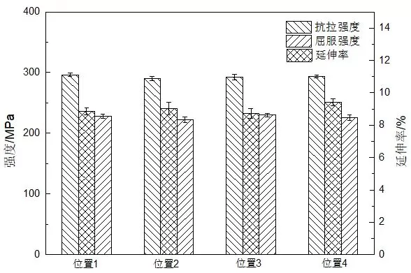
Figure 8: Mechanical properties of squeeze cast control arm
Figure 9 shows CT photographs of the cast without and with partial squeeze casting. It can be seen from Figure 9a that obvious shrinkage defects appear at the mounting holes of the casting without local extrusion, and such defects can be eliminated by applying local extrusion, as shown in Figure 9b. It should be noted that the insertion depth of the extrusion needle during the local extrusion process depends not only on the pressure of the local extrusion cylinder, but also on the insertion time and the solidification of the casting. Although the casting defects were eliminated by local pressurization in this project, the depth of the extrusion needle insertion was not enough, which did not contribute much to the formation of the mounting hole, and subsequent machining was required to complete it.
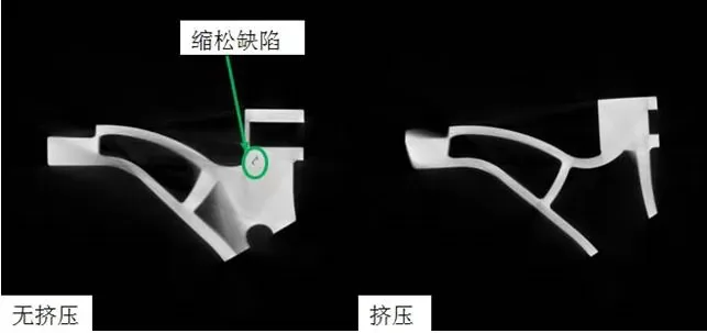
Figure 9: Influence of local squeeze casting on casting quality
4 Conclusion
(1) Through the structural topology optimization design, a lightweight cast aluminum alloy control arm was developed on the basis of the original steel control arm, which achieved the set goal of reducing weight by 25%, and passed the test of the main engine factory, and other performances did not decrease.
(2) The development of the casting was completed by the squeeze casting process, and the local extrusion technology was introduced, which effectively eliminated the defects that could not be eliminated by increasing the holding time and boosting pressure. The tensile strength was 293.2 MPa and the yield strength was 226.48 MPa, elongation 9.01%.
(3) The design and test show that the steel-aluminum hybrid structure control arm with the aluminum alloy casting as the core can meet the use requirements of the lower control arm, and greatly reduce the quality to meet the needs of the lightweight of the whole vehicle.

.png)


.png)
.png)
.png)

.png)


.png)

.png)

 +86-574-83008051
 sales@innovaw.com


.png)