Abstract|ZL105A alloy is used to produce rocker shell castings. According to the structural characteristics and performance requirements of ZL105A alloy and castings, the comprehensive performance optimization of ZL105A alloy was carried out from four aspects: melt refining, alloying, casting process design and ProCAST simulation, and the casting process of rocker shell castings was analyzed. gist. The results show that the comprehensive mechanical properties of ZL105A alloy can be effectively improved by using hexachloroethane and argon rotary blowing compound refining, combined with Be alloying. The low-pressure sand casting process, combined with the bottom casting + gap casting system and the method of placing cold iron in thick and large parts, can produce rocker shell castings with good internal quality, with the highest tensile strength, yield strength and elongation of the casting body. Up to 318 MPa, 261 MPa, 5.6%, the body fatigue performance, internal quality and size all meet the design requirements.
High-speed maglev train is a key development object in my country's transportation field. The aluminum alloy casting of the rocker shell is the key bearing component of the traveling system of the high-speed maglev vehicle with a speed of 600 km/h. It has high requirements on the mechanical properties and fatigue performance of the body. The quality of the casting is directly related to the safety and reliability of the vehicle. . In order to break through the foreign supply blockade, in order to realize the independent supply guarantee of key components of my country's 600 km and above wheelless high-speed trains, and to form independent intellectual property rights and complete technical iterative upgrades, the localization development of rocker shell castings is of great significance. .
This subject has high requirements for comprehensive performance of rocker shell castings. In addition to the higher mechanical properties of the body, it also puts forward clear requirements for the body fatigue properties of the castings and the reliability of the entire part. The ZL105A alloy used in the casting is a cast Al-Si-Cu alloy containing about 1% Cu, which has higher strength and better air tightness than ZL101A. This subject takes the rocker shell casting as the research object, comprehensively considers the alloy characteristics, the structural characteristics and service requirements of the casting, and analyzes and studies from the pouring process, melt treatment, etc. Parts provide process design reference.
1 Structural characteristics and technical requirements of castings
The overall size of the rocker shell casting is about 1 200 mm × 160 mm × 80 mm (see Figure 1); the casting is an overall flat plate structure, and the wall thickness is small (the average wall thickness is about 4 mm), and there are many hot spots . For Class I castings, the mechanical properties are required to be cut from the body: tensile strength ≥ 280 MPa, yield strength ≥ 235 MPa, and elongation ≥ 3%. The casting needs to withstand at least 10 million fatigue cyclic loads, and the cutting fatigue performance of the casting body is required to meet: when R=-1 and the maximum fatigue stress is 90 MPa, the fatigue life is not less than 107 times.
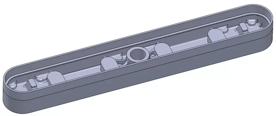
Figure 1: 3D Model of Rocker Housing Casting
2 Test materials and methods
The castings are made of ZL105A alloy, and the chemical composition meets the requirements of GB/T 1173-2013. The alloy was smelted in a resistance furnace. The high-purity aluminum, Al-12Si, and Al-50Cu master alloys were put into a cast iron crucible, kept at 850 °C until the melting was completed, and stirred for 30 min; cooled to 700 °C, pure Mg was added, and the melt was melted. Stir for 15 min. The melt was degassed and slag removed by using different mass fractions [0.6%, 0.78% of refining agent (C2Cl6)] and Ar refining and blowing for 20 min, and Al-5Ti-1B wire was added for refinement treatment. Low-pressure casting was used for production, and the chemical composition of the obtained castings is shown in Table 1.
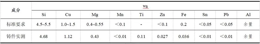
Table 1: Chemical composition of castings %
The castings were subjected to T6 heat treatment (525 ℃ × 6 h solution, water quenching, 160 ℃ × 5 h aging). The room temperature tensile properties and high-circumferential axial fatigue properties were tested on the MTS-Landmark testing machine, and the sample size met the requirements of GB/T 228.1-2010 [4]. The tensile rate was 1 mm/min, the fatigue test stress ratio was R=-1, the maximum stress was 90 MPa, and the loading frequency was 120 Hz. The microstructure of the castings was observed with a LEICA DM1750M metallographic microscope, and the tensile fracture structure was observed with a Sigma 300 scanning electron microscope. The hydrogen content of the melt was measured by an RT-CQ1000 aluminum melt hydrogen tester.
3 Test results and discussion
3.1 ZL105A alloy melt treatment
Rocker shell castings need to have good body fatigue performance, which requires the microstructure of the castings to be dense, and strictly prevent the existence of shrinkage porosity and crack defects, and it is necessary to focus on controlling the degree of pinhole defects in the castings. The Si content in ZL105A alloy is 4.5%~5.5%, and the Mg content is 0.40%~0.55%. The alloy has a serious tendency to absorb H and is prone to pinholes. Under the conventional melting method, there is more H dissolved in the melt. During the solidification process, it is easy to produce excessive pinhole defects, so the method of strengthening refining is used to reduce the pinhole degree in the casting.
Figure 2 shows the fracture of the test block before and after enhanced refining. It can be seen from Figure 2a that the melt fracture after refining is gray, and there are obvious large-sized white spots (pinholes) and a small amount of black inclusions on the fracture surface. After increasing the amount of refining agent, and then using high-purity argon injection treatment (injection for 20 min), the fracture is shown in Figure 2b. It can be seen that the number of white spots (pinholes) on the section is significantly reduced and the size of the white spots is significantly smaller. The melt metallurgical quality Significant improvement. In the refining process, the Cl2 generated by the decomposition of C2Cl6 at high temperature is discharged from the alloy liquid in the form of small bubbles, and the slag is adsorbed and discharged together. At the same time, due to the partial pressure of H, Cl2 can adsorb and dissolve part of the alloy liquid. H, but due to the large and small number of bubbles formed by C2Cl6 refining, the H absorption effect is not ideal; and the high-purity argon injection method uses equipment control to reduce the size of the bubbles, which can better adsorb H in the alloy liquid , but because the bubbles are too small, the buoyancy is insufficient, and the slag discharge effect is slightly poor. Therefore, using an appropriate amount of C2Cl6 refining and refining with high-purity argon gas can obtain a better melt effect.
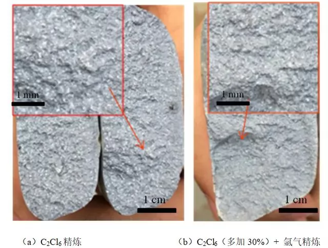
Figure 2: Fracture morphology analysis under different refining processes
Figure 3 shows the high-power metallographic structure of the single-cast test bar with and without Be added to the alloy (the addition of Be is 0.15%). Table 2 shows the comparison of the hydrogen content of the melt with and without Be. It can be seen that the hydrogen content of the aluminum melt with Be added is significantly lower than that without Be, and the eutectic Si phase of the aluminum melt with Be added is finer, which is consistent with the research conclusion of Morteza R et al. Due to the presence of Fe in the melt, Be and Fe form a Be-Fe precipitation phase. The crystallization temperature of this phase is higher than the crystallization temperature of eutectic Si, and it acts as the nucleation core of eutectic Si during the solidification process, resulting in a certain amount of eutectic Si. Refinement effect. At the same time, due to the existence of Be, it will first combine with O to form BeO with increased volume, which closes the oxide film cracks on all exposed surfaces including the new surface generated when the alloy flows, slows down the oxidation rate of the alloy liquid, and reduces the absorption of H in the melt. , maintaining the internal purity of the alloy.
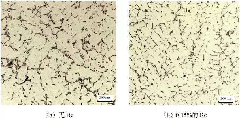
Figure 3: Microstructure of ZL105A alloy

Table 2: Hydrogen content μg/g in ZL105A alloy aluminum liquid with and without Be added
3.2 Casting process design and numerical simulation
There is a hot joint area in the casting of the rocker shell locally, so the inner runner is set below the hot joint to avoid the internal shrinkage defect caused by insufficient feeding. Since the height of the casting is only 160 mm, the width is 80 mm, and the average wall thickness of the façade is only 4 mm, considering the modeling, ease of unpacking and feeding effectiveness, the bottom pouring + slot pouring system is adopted. Formed by low pressure casting (see Figure 4). Based on this gating system, the rationality of the casting process is calculated.
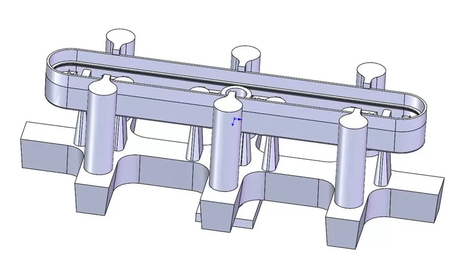
Figure 4: Schematic diagram of the design of the gating system for the rocker shell
Using ProCAST simulation software, the casting process of the rocker shell casting is simulated and calculated, and the casting process parameters used in the simulation are shown in Table 3.

Table 3: Pouring process parameters
Figures 5 and 6 show the temperature field and solid phase ratio during the solidification process of the rocker shell, respectively. It can be seen that the temperature gradient distribution of the rocker shell casting is reasonable during the solidification process after the molten metal is filled. microstructure and high mechanical properties.
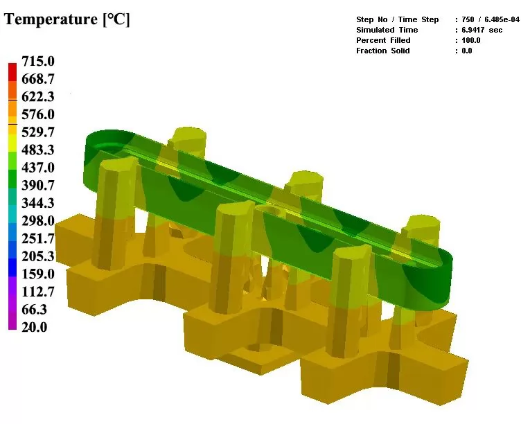
Figure 5: Temperature field during solidification of rocker shell
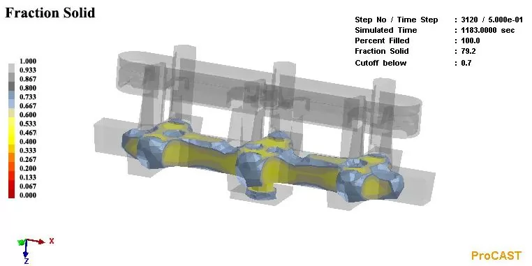
Figure 6: Solid phase rate during solidification of rocker shell
Figure 7 shows the possible locations of shrinkage according to the Niyama criterion. The simulation results show that under this process condition, the hot joints are effectively fed, and the whole casting has no shrinkage porosity. Figure 8 shows the pressure distribution and transfer of molten aluminum during the simulated filling process. It can be seen that the aluminum liquid pressure gradually decreases from bottom to top during low-pressure filling, and a good sequential solidification pressure gradient is established, which can achieve effective feeding of the casting.
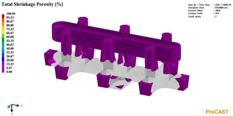
Figure 7: Shrinkage of rocker shell during solidification
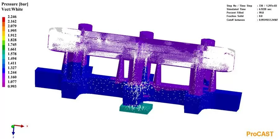
Figure 8: Pressure distribution during casting of rocker shell
Based on the above simulation results, it can be seen that the casting process design of the rocker shell casting is reasonable. In addition, in order to further ensure the internal quality of the casting in the actual production process, a conformal chilled iron (the thickness of the chilled iron is 10 mm, see the red area in Figure 9) is set up in the thick part to speed up the chilling; at the same time, in the runner A filter screen is installed at the intersection with the inner runner to reduce the risk of inclusions in the casting body.
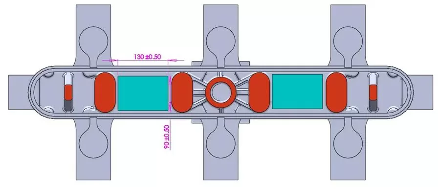
Figure 9: Schematic diagram of cold iron arrangement and body cutting position
4 Production verification
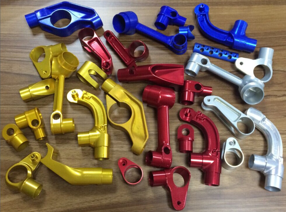
The rocker shell casting is produced according to the above process, and the actual casting is shown in Figure 10. After X-ray inspection, no shrinkage defects were found inside the casting, which is consistent with the simulation calculation results of Procast; no pinholes and inclusions were found in the casting, and the internal quality met the requirements of GB 9438-2008 Class I castings, and a successful trial production was achieved. The three-coordinate test platform is used to conduct dimensional inspection of the rocker shell, and all the dimensions are qualified. The castings are dissected, and the mechanical properties and fatigue properties of the rocker shell castings are shown in Table 4, all of which meet the technical requirements. The tensile fracture of the sample cut from the body is shown in Figure 11. It can be seen that there are a large number of tearing edges on the entire section, and the fracture shows more dimples and small cleavage planes. The number of dimples is large, and the depth is deep, showing toughness Mixed fracture of fracture and cleavage fracture. There are no obvious defects such as shrinkage porosity and pores on the fracture surface, and the overall plasticity is good.
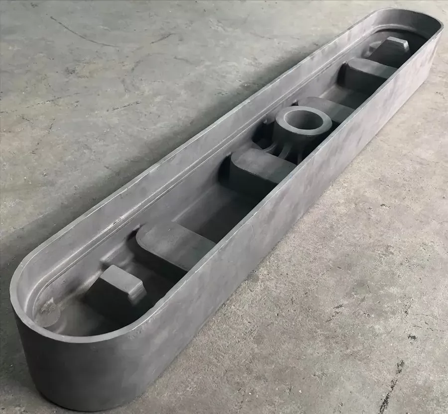
Figure 10: Qualified rocker housing casting
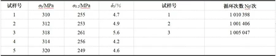
Table 4: Mechanical Properties and Fatigue Life of Casting Body Sampling
Figure 12 shows the fracture morphology of the fatigue specimen of the rocker shell body. It can be seen that the crack source is near the surface (defects such as oxides, shrinkage porosity and pinholes are not observed at the crack source, and the crack source or the stress concentration part of the test bar is processed), and the crack initiation and expansion area accounts for the proportion of the entire fracture. larger (nearly 40%), showing good fatigue properties. Some bright planes were found in the crack propagation area, which may be caused by the mutual abrasion of the upper and lower planes during the crack propagation process. In the instantaneous fracture area, a large number of tear edges and small dimples can be seen, mainly plastic fracture and mixed cleavage fracture, showing good plasticity, which is consistent with the characteristics of the tensile fracture surface.
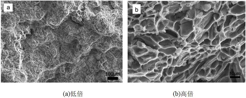
Figure 11: Tensile fracture structure of casting body
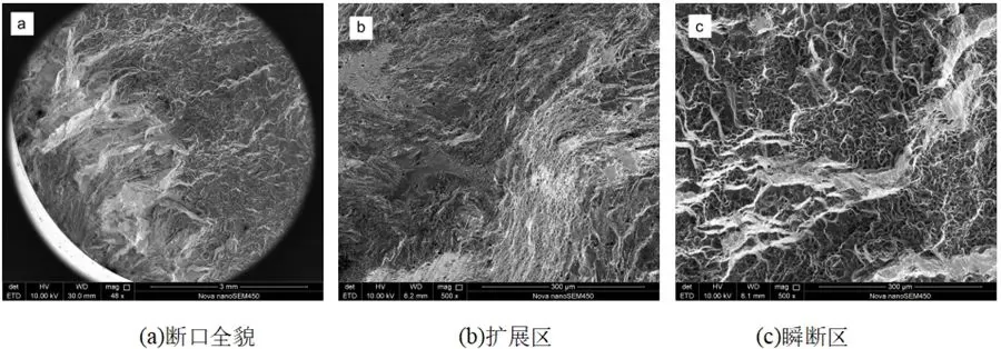
Figure 12: Bulk fatigue fracture structure of castings
5 Conclusion
(1) By compound refining and adding Be, the sampling performance of ZL105A rocker shell casting body: tensile strength is 318 MPa, yield strength is 261 MPa, elongation is 5.6%, fatigue life is more than 107 times, and the casting shows good performance comprehensive performance.
(2) Based on the simulation calculation results of ProCAST, the low-pressure sand casting method was used, and the bottom casting + slot casting process was used to develop the rocker shell casting with qualified internal quality.

.png)


.png)
.png)
.png)

.png)


.png)

.png)

 +86-574-83008051
 sales@innovaw.com


.png)